
- Use click plc as modbus server manuals#
- Use click plc as modbus server manual#
- Use click plc as modbus server software#
- Use click plc as modbus server series#
Communication ability - Ethernet Port, RS232, RS485 - support for protocols such as Modbus RTU, Modbus TCP, etc.
Use click plc as modbus server software#
Investment is low for the hardware and the software is free There are several reasons why we are using the Click PLC.
Use click plc as modbus server series#
The entire Click PLC series can be found at this URL: Stride Field Remote IO Modules Powering and Configuring

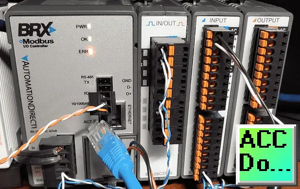
Stride Field Remote IO Modules Unboxing SIO MB12CDR and SIO MB04ADS The most common use of the protocols at this time is for Ethernet attachment of PLCs, I/O modules and gateways to other simple field buses or I/O networks. PID Instruction and Autotuning using Factory IO Modbus RTU Click PLC Master to BRX PLC Slave Communicationįrequency Measurement and High-Speed Count Mode This includes all of the links mentioned in this video.Ĭlick PLC Numbering System and Addressing More information can be obtained on our website. Our Click PLC program will also take into consideration watchdog (communication time out) and power-up events for the Stride remote input and output units. We will look at the Frequency, Count, and Status of this input. The output will be on the other remote IO unit and will trigger the input to signal. We will then set an output to pulse on and off at a time range indicated by this analog signal. We will be reading an analog voltage into the Click PLC from the remote IO unit. STRIDE analog input module, 4-channel, current/voltage, 16-bit, isolated, input current signal range(s) of +/- 20 mA, input voltage signal range(s) of +/- 10 VDC, (1) Ethernet (RJ45) port(s), Modbus TCP server. STRIDE discrete combo module, Input: 8-point, 12-24 VDC, sinking, Output: 4-point, relay, (4) Form C (SPDT) relays, 2A/point, (1) Ethernet (RJ45) port(s), Modbus TCP server. Modbus TCP will be the protocol over Ethernet to communicate to the SIO-MB12CDR and SIO-MB04ADS units. We will be connecting two Stride remote inputs and outputs to the Click PLC. Unboxing SIO MB12CDR and SIO MB04ADS Video Stride Field Remote IO Modules Modbus TCP Ethernet Previously we looked at the Stride Field Remote IO Modules Modbus TCP Ethernet wiring and configuration.

Every module operates as a standalone Modbus TCP server and can be configured via a built-in web server. They provide an economical means to connect inputs and outputs to an Ethernet Modbus TCP communication network. The Stride Field I/O Modules are simple and compact. When a transmission error occurs, specify the SJ-Ether device that stores the error details.The Click PLC can use remote inputs and outputs from Stride. Specify the SJ-Ether device to be used as the transmission error flag. Specify the SJ-Ether device to be used as the transmission success flag. Specify the SJ-Ether device to be used as the sending flag. Specify the TCP port number to use when writing. Specify the IP address of the other device you want to write to. Specify the size of the data you want to write. SJ-Which data of Ether is written to the other party. Specify the start address of the device you want to write to. Specify the function to be used when writing. When a reception error occurs, specify the SJ-Ether device that stores the error details. Specify the SJ-Ether device to be used as the reception error flag. Specify the SJ-Ether device to be used as the reception success flag. Specify the SJ-Ether device to be used as the receiving flag. Specify the TCP port number to be used when reading.

Specify the IP address of the other device you want to read. Specify the size of the data you want to read. Where to bring the read data to SJ-Ether. Specify the start address of the device you want to read. Specify the function to be used when reading.
Use click plc as modbus server manuals#
3 fixed.Ĭheck the manuals of each slave product company. The details of the ERX / EWX instruction are explained in detail in the help of KPP. (7) If you want to read the data of the slave station into SJ-Ether, use the ERX instruction. (6) If you want to write data from SJ-Ether to the slave station, use the EWX instruction. (5) The server (slave) setting may be the factory default value, but if it overlaps with the TCP port number you want to use at the master station, change it. (4) Set the timeout / retry count / timeout time in the client (master) settings. (3) Click “Modbus / TCP Clients and Servers”. (2) Check “Modbus / TCP Client and Server” for protocol settings. (1) Set the IP address and subnet mask of SJ-Ether in Port3 of “PLC”-> “PLC setting”-> “general-purpose communication port setting” of KPP (Koyo PLC Programming software). The outline of the procedure for using SJ-Ether is as follows.
Use click plc as modbus server manual#
(For slave station settings, see the product manual of each company you are using.) For details, see Chapter 4 4-4 MODBUS / TCP Communication in the SJ-Ether User’s Manual.


 0 kommentar(er)
